| magnetic flux the integration area of which is such that magnetic field lines cross it in the same orientation more than once
Note 1 to entry: Linked flux is observed in two different situations:
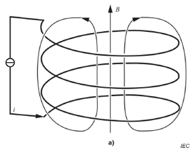
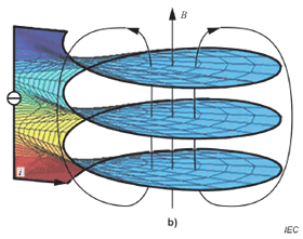
1) when the magnetic field is produced by a circuit carrying a current (see Figure 1) and
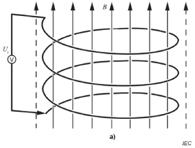
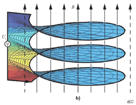
2) when the magnetic field is produced by an external source (see Figure 2).
 
Figure 1 – A typical example for linked flux is a coil producing a magnetic flux due to a current i
In Figure 1a), the magnetic field lines (B) link the windings of the coil.
In Figure 1b), the magnetic field lines (B) penetrate the slices of the surface in the same orientation.
The magnetic field of the line closing the circuit is neglected.
 
Figure 2 – A second typical example for linked flux is a coil in a homogeneous magnetic field represented by the magnetic flux density B varying in time producing an induced voltage U
i
In Figure 2a), the magnetic field lines are linked by the windings of the coil (solid lines), the magnetic field outside (dashed lines) is not included in the flux.
In Figure 2b), the magnetic field lines (B) penetrate the slices of the surface in the same orientation.
The magnetic field at the lines closing the circuit is perpendicular to the integration area, and thus the linked flux is zero in this area.
Note 2 to entry: For a coil with N windings, the linked flux is Ψl=NΦ1, where Φ1 is the magnetic flux through a surface corresponding to one average winding, considered to be closed.
Note 3 to entry: The coherent SI unit of linked flux is weber, Wb = kg m2 s−2 A−1.
|